Wikipedia

Search results

Latest On IndianDIYers

Coconut Shell Lamp

Follow Me


NAV

Showing posts with label Arduino Project. Show all posts

Thursday, 15 October 2020

Fingerprint Based Voting Machine Using Arduino and Finger print sensor.

 Fingerprint Based Biometric Voting Machine Using Arduino


We all are aware of the existing electronic voting machine where the user has to press a button to cast the vote. But these machines have been criticized for tempering since the beginning. So the government is planning to introduce a fingerprint-based voting machine where users can cast the vote based on his/her fingerprint impression. This system will not only remove the possibility of duplicate votes but also prevent any kind of manipulation.So in this project, we are going to build a prototype of a Biometric voting machine using the Arduino Uno, TFT display, and Fingerprint Sensor.


Step 1: Components Required to Build Biometric Voting Machine


Arduino Uno

2.4” TFT LCD Display Shield

GT-511C3 Fingerprint Sensor


Circuit Diagram

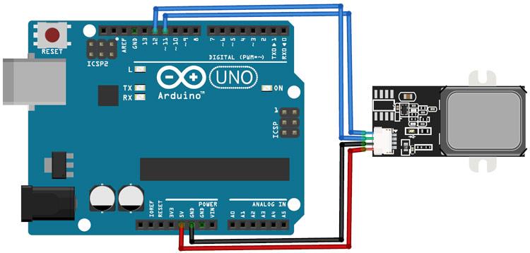
Circuit Diagram for Biometric Voting Machine Using Arduino

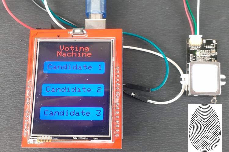
 Circuit Diagram for this project is very simple as we are only connecting the TFT display and fingerprint sensor module with Arduino Uno. VCC and GND pins of the fingerprint sensor are connected to 5V and GND pins of Arduino while TX and RX pins are connected to digital pin 11 & 12 of Arduino Uno.The 2.4” TFT LCD screen is an Arduino Shield and can be directly mounted on Arduino Uno, as shown in the below image. TFT display has 28 pins that perfectly fit into Arduino Uno, so I had to solder the fingerprint sensor on the backside of Arduino.


Step 3: Source Code and Step by Step Code Explanation

The complete code for this Fingerprint Voting System Project using Arduino is given at the end of the article; here we are explaining some important functions of the code.
The code uses the SPFD5408, Software Serial, and FPS_GT511C3 libraries. SPFD5408 library is the modified version of the original Adafruit Library. These library files can be downloaded from the links given below:

After including the libraries and defining some important parameters, we can get into the programming part. There are three sections involved in this program. One is creating a UI of a voting machine, second is getting the touch-points for buttons & detecting the buttons based on the touch and finally calculating the results and save them into Arduino’s memory.

1. Creating UI:

I have created a simple UI with three buttons and the name of the project. The TFT display library allows you to draw Lines, Rectangle, Circles, Chars, Strings and a lot more of any preferred color and size. Here two rectangular buttons are created using fillRoundRect and drawRoundRect functions. Syntax for tft.drawRoundRect function is given below:


tft.drawRoundRect(int16_t x0, int16_t y0, int16_t w, int16_t h, int16_t radius, uint16_t color)
Where:
x0= X co-ordinate of the starting point of rectangular
y0= Y coordinate of the starting point of rectangular
w = Width of the rectangular
h = Height of the Rectangular
radius= Radius of the round corner
color = Colour of the Rect.
void drawHome()
{
tft.fillScreen(WHITE);
tft.drawRoundRect(0, 0, 319, 240, 8, WHITE); //Page border
tft.fillRoundRect(10, 70, 220, 50, 8, GOLD);
tft.drawRoundRect(10, 70, 220, 50, 8, WHITE); //Vote
tft.fillRoundRect(10, 160, 220, 50, 8, GOLD);
tft.drawRoundRect(10, 160, 220, 50, 8, WHITE); //Enroll
tft.fillRoundRect(10, 250, 220, 50, 8, GOLD); //Result
tft.drawRoundRect(10, 250, 220, 50, 8, WHITE);
tft.setCursor(65, 5);
tft.setTextSize(3);
tft.setTextColor(CYAN);
tft.print("Voting");
tft.setCursor(57, 29);
tft.print("Machine");
tft.setTextSize(3);
tft.setTextColor(WHITE);
tft.setCursor(25, 82);
tft.print("Candidate 1");
tft.setCursor(25, 172);
tft.print("Candidate 2");
tft.setCursor(25, 262);
tft.print("Candidate 3");
}


2. Getting the Touch-Points and Detecting Buttons:


Now in the second section of the code, we will detect the button touchpoints and then use these points to predict the button. ts.getPoint() function is used to detect the user touch on TFT display. ts.getPoint gives the Raw ADC values for the touched area. These RAW ADC values are then converted to Pixel Coordinates using the map function.
TSPoint p = ts.getPoint();
if (p.z > ts.pressureThreshhold)
{
p.x = map(p.x, TS_MAXX, TS_MINX, 0, 320);
p.y = map(p.y, TS_MAXY, TS_MINY, 0, 240);
//Serial.print("X:");
//Serial.print(p.x);
//Serial.print("Y:");
//Serial.print(p.y);
Now, since we know the X and Y coordinates for each button, we can predict where the user has touched by using the ‘if’ statement.
if (p.x > 70 && p.x < 120 && p.y > 10 && p.y < 220 && p.z > MINPRESSURE && p.z < MAXPRESSURE)
{
Serial.println("Candidate 1");
When a voter presses the candidate button, he will be asked to scan the finger on the fingerprint sensor. If finger ID is authorized then the voter is allowed to vote. If any Non-registered user wants to vote then the fingerprint module will not detect its ID into the system and the display will show ‘Sorry You Can’t Vote ’.
if (fps.IsPressFinger())
{
fps.CaptureFinger(false);
int id = fps.Identify1_N();
if (id <200)
{
msg = "Candidate 1";
vote1++;
EEPROM.write(0, vote1);
tft.setCursor(42, 170);
tft.print("Thank You");
delay(3000);
drawHome();


3. Result:

The last step is getting the vote count from EEPROM memory and comparing the votes of all three candidates. A Candidate with the highest votes wins. The result can only be accessed from the serial monitor and will not be displayed on the TFT screen.
vote1=EEPROM.read(0);
vote2=EEPROM.read(1);
vote3=EEPROM.read(2);
if(vote)
{
if((vote1 > vote2 && vote1 > vote3))
{
Serial.print("Can1 Wins");
delay(2000);
}

Step 4: Testing the Fingerprint Voting System Using Arduino


To test the project, connect the Arduino Uno to the laptop and upload the given code. Once the code is uploaded, the TFT display should display the candidate’s name. When someone taps on a candidate name, the machine will ask to scan the fingerprint scanner. If the fingerprint is valid, then the user vote will be counted, but in case, the pattern doesn’t match with the records of the database, access to cast a vote will be denied. The total number of votes for each candidate will be stored in EEPROM and a candidate having the highest number of votes will win.


Sunday, 4 November 2018

How to Make Solar Tracker Using Arduino and Servo Motor


Introduction:-In this post I am going to talk about the "solar Tracker" which I've made using a Arduino UNO and SG90 servo. Before reading the post please check the video from my channel , it gives 70% of Idea about the project. So I've made a solar tracker using an arduino and servo motor. This solar tracker uses two LDRs to measure the light or the resistance of the LDR changes according to the light. It can also charge mobile phone.....Click Here for more projects...


Check This Video......


Step:-1-Parts and Materials
Please use this links to buy the the products used in this project...So I can rise some funds for my future projects....You don't have to pay more the price will be same.
****Amazon INDIA****
*****Gearbest*****
2) LDR x 2
Picture of Step:-1-Parts and Materials

Picture of Step:-1-Parts and Materials

Picture of Step:-1-Parts and Materials

Picture of Step:-1-Parts and Materials

Picture of Step:-1-Parts and Materials

Picture of Step:-1-Parts and Materials

Picture of Step:-1-Parts and Materials

Picture of Step:-1-Parts and Materials


Step:2- Making Body

I've used wood to make the body for the solar tracker, It's a triangular shaped wood which allows the solar panel to move in one axis the wood is of random size and you can make this as your requirement. I've used old pens to connect the both wood.

Picture of Step:2- Making Body


 Make a hole on the upper side of the wood so we can mount the servo there later. Check the video and images for reference.

Picture of Step:2- Making Body

Picture of Step:2- Making Body

Picture of Step:2- Making Body

Picture of Step:2- Making Body

Picture of Step:2- Making Body

Picture of Step:2- Making Body

Picture of Step:2- Making Body


Step:3-Schematics & Software


Picture of Step:3-Schematics & Software
First download the ZIP file and extract it, you will find a circuit diagram of the project. The signal wire of the servo is connected to Digital pin 9 of the arduino and GND>>GND & Vcc>>5V of arduino, One terminal of the LDR1 and LDR2 is short circuited and connected to the 5V pin of arduino and other terminal of the LDRs is connected to the pin A0 and A1 of the arduino.
                      *****Click Here to Download ZIP file*****
Complete the circuit and Upload the arduino Sketch to the arduino.
Picture of Step:3-Schematics & Software


Step:4- Mounting the Servo and Solarpanel

Connect the servo rod in my case plastic pipe and mount the servo on the wooden frame(body) using hot glue and also glue the servo rod with solar panel "make sure that the servo moves equal distance in both direction". And finally glue the both LDRs on the solar panel as shown in video or image.

Picture of Step:4- Mounting the Servo and Solarpanel

Picture of Step:4- Mounting the Servo and Solarpanel

Picture of Step:4- Mounting the Servo and Solarpanel

Thanks for visiting my instructables and Visit My Youtube channel. ....Support my projects.....Visit My facebook and visit on Twitter...

Thursday, 12 July 2018

How to Make Scrolling Display Using Arduino and Bluetooth | DIY smartphone control scrolling display using arduino

Introduction:-

In this post I am going to discuss about "How can you make a scrolling display using the arduino and control it through smartphone" . By using the Bluetooth you can send maximum 63 characters and through the program it can display up to 500 characters (In my case). The message from Bluetooth is temporary and it will automatically clear if the micro-controller is turned off. Before starting please watch the Video it gives you the whole Idea about the project,,,,and if you like the video then don't forget to leave the like and comment and share the video......So.let's get started....

Step 1: Materials and Tools

1) Bread Board
2) 2pcs Of DMD (dot-matrix-display) mine is P10
3) Arduino UNO or NANO
4) HC-05 Bluetooth module
5) Jumper Wires
6) Wire stripper
7) Screwdriver
8) 5 Volt DC adapter (Higher the Amp better the brightness "max-5 amp")

Step 2: Circuit


Connect the DMD pins as shown in the circuit diagram and connect the output of the first module to the input of the second module and also connect the Vcc and GND of the both panel using wires.
Connection of led panel with arduino UNO
OE >>> D9
A >>> D6
B >>> D7
C >>> No connection
CLK >>> D13
SCLK >>> D8
R >>> D11
GND >>> GND of arduino( any one)
Bluetooth Connection
Connect the TX of the Bluetooth module to the RX (D0) pin of the arduino and RX of bt. module to TX (D1) of arduino UNO...
You can also change the Password and Name of the bluetooth module using AT command to ahange the password and name connect TX of Bt. module to TX of UNO and RX to RX and Open Arduino IDE and open Serian monitor Type AT command. You can find all AT command of HC-05 Module on internet " search for 'AT command of HC-05' on google"
NOTE***---You Cant upload the program while bluetooth is connected to the arduino.


Step 3: Upload the Program


Before uploading sketch to arduino disconnect the bluetooth module from arduino to avoid compiling error.
Download the zip file which contents TimerOne and DMD library and the arduino Sketch, and extract the zip file. copy the libraries to the library folder of arduino and open the arduino sketch. You can change the max characters length and message on the program as your requirement. ...
Chose the board type and serial port and click upload...after uploading the sketch connect the bluetooth module and you are ready to send message using smartphone....
Arduino sketch Credit: to hackers.io

Step 4 :Installing App and Connecting Power Supply


Now connect the 5 volt DC power supply to LED panel and power it on if it is working perfectly...Then install the bluetooth control app from google play store. Open play store and search for "Arduino Bluetooth Control" and install the app and open and connect with bluetooth module...and you are ready to send mesasage....
If You found this post helpful then leave a like and consider supporting my future projects through my patreon campaign and subscribe to my youtube channel....