 Since the 1990s, the world has been invaded by PCs. The situation continues to this day. Older computers, until 2014 ... 2015, are largely out of use.As each PC has a power supply, there are a large number of them abandoned in the form of waste.Their number is so large that they raise environmental issues.Their recovery contributes to saving the environment.If we add to this the fact that we can use many of the components and materials that make them up, to do various things, it is understandable why it is worth make this.In the main photo you can see only a small part of the power supplies that I dealt with in this regard.In general, there are 2 ways to follow:1. Use of power supplies as such (after a possible repair).2. Disassembly and use of component parts for various other purposes.As point 1 has been extensively presented elsewhere, I will focus on point 2.I will present in this first part what can be recovered and where what I recovered can be used, following that in future Instructables concrete applications are presented, with what I recovered.
Step 1: A Little Theory: Block Diagram
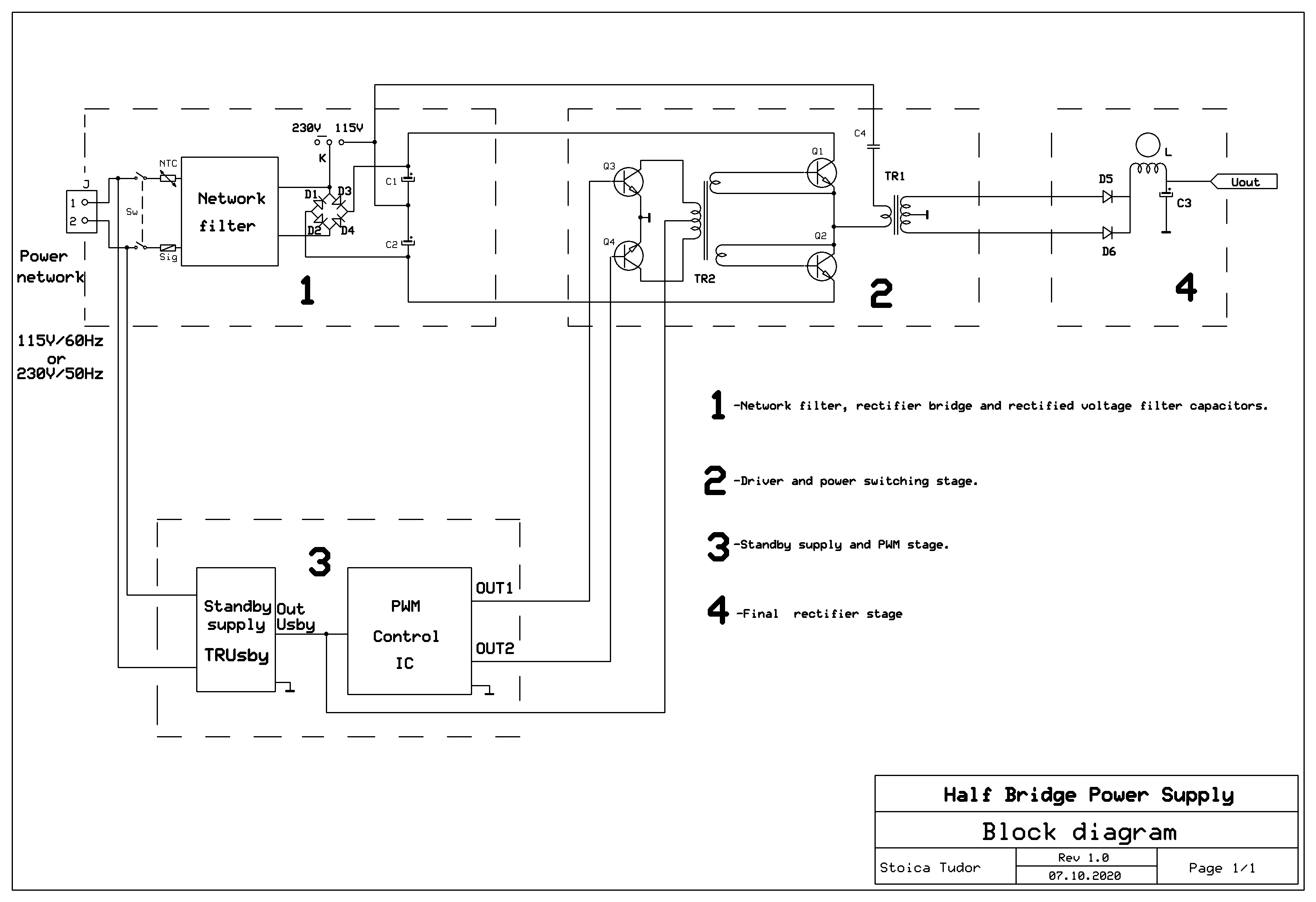
It seems strange to start with a bit of theory a practical work, but it is important to understand what is worth recovering from such a power supply and where it can be used.
So we need to know what's inside and how it works.
I can't say that all the power supplies from the mentioned period had this block diagram, but the vast majority did.
In addition, there is a wide variety of schemes starting from this, each with specific circuits. But broadly speaking, this is how things are:
1.Network filter, rectifier bridge and rectified voltage filter capacitors.
Power network applies to J connector. Follow a fuse (or two) that burns in case of power failure.
The component marked with NTC has a higher value at the start of the power supply, then decreases with increasing temperature. Thus, the diodes in the bridge are protected at the start of the power supply, by limiting the currents in the circuit.
Next is the network filter, which has the role of limiting the disturbances introduced by the power supply. in the power network.
Then there is the bridge formed by diodes D1 ... D4 and in addition to some power supplies the switch K.
For K on the 230V / 50Hz position, D1 ... D4 forms a Graetz bridge. For K on the 115V / 60Hz position, D1 and D2 together with C1 and C2 form a voltage doubler, D3 and D4 being permanently locked.
In both cases, on the C1 series with C2 assembly we have 320V DC (160V DC on each capacitor).
2. Driver and power switching stage.
It is a Half Bridge Stage, where the switching transistors are Q1 and Q2.
The other part of the half-bridge consists of C1 and C2.
The primary coil of theTR1 chopper transformer is connected diagonally to this half-bridge.
TR2 is the driver transformer . It is controlled in primary by Q3, Q4, driver transistors . In secondary, TR2 commanded in antiphase Q1, Q2.
3. Standby supply and PWM stage.
Standby supply is powered at the input with power network and offer at the output Usby (usually + 5V).
This is itself a switching power supply built around a transformer notated TRUsby.
It is necessary to start the source, being then usually taken over by another voltage generated by the power supply.
PWM control IC is a circuit specialized in the anti-phase control of transistors Q3, Q4, performing PWM control of the source, stabilization of the output voltages, protections against short-circuit in load, etc.
4.Final rectifier stage.
In fact, there are several such circuits, one for each output voltage.D5, D6 diodes are fast, high current Schottky diodes are often used on the + 5V branch.Inductors L and C3 filter the output voltage.Step 2: Initial Disassembly of the Power Supply
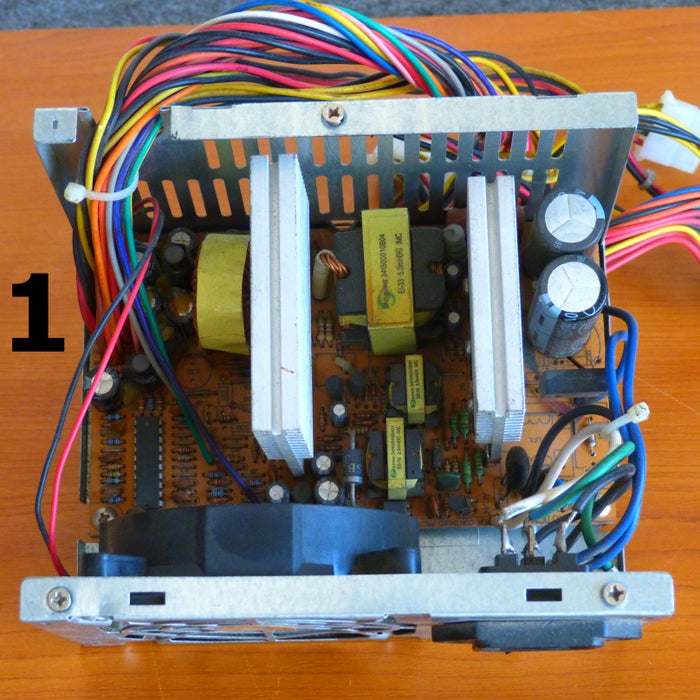
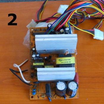
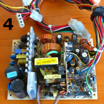
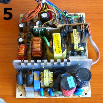
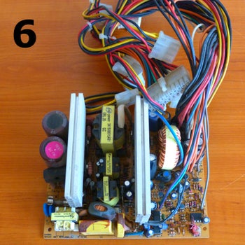
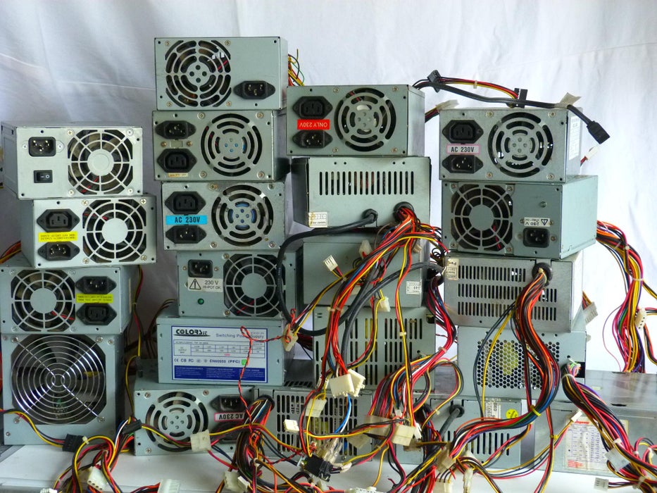
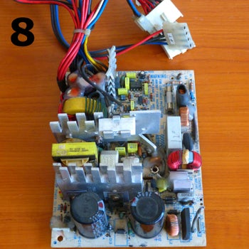
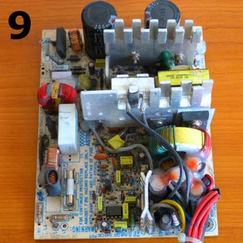
The first step is to remove the power supply cover. The general organization is the one seen in photo 1.The board with electronic components can be seen in photos 2,3.In photos 3 ... 9 you can see other boards with electronic components.In all these photos are highlighted the most important electronic components, which will be recovered, but also other subassemblies of interest. Where appropriate, the notations are those in the block diagram.
Step 3: Capacitors Recovery
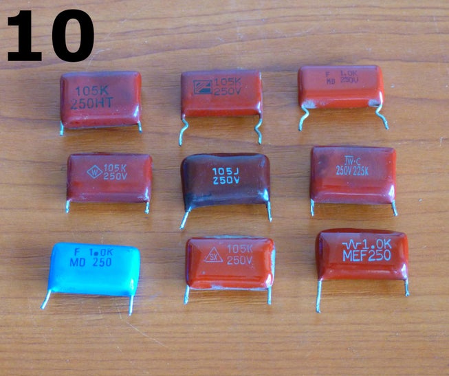
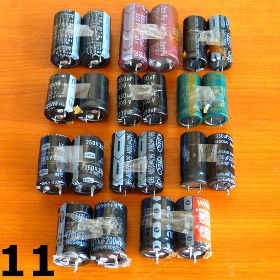
With the exception of the capacitors in the Network Filter, it is recommended to recover only the following capacitors:-C4 (see photo10) 1uF/250V, pulse capacitors.It is the capacitor coupled in series with the primary TR1 (chopper), which has the role of cutting any continuous component caused by the imbalance of the half bridge and which would magnetize in DC. TR1 core.Usually the C4 is in good condition and can be used on other similar power supplies, having the same role.-C1, C2 (see photo11) 330uf/250V...470uF/250V , value that depends on the power supplied by the power supply.They are usually in good condition. It is checked to have a maximum deviation of +/- 5% between them.I found in some cases that although a value was marked (for example 470uF), in reality the value was lower. If the two values are balanced (+/- 5%) it is OK.Pairs are kept, as they were recovered, as in photo11.
Step 4: NTC Recovery
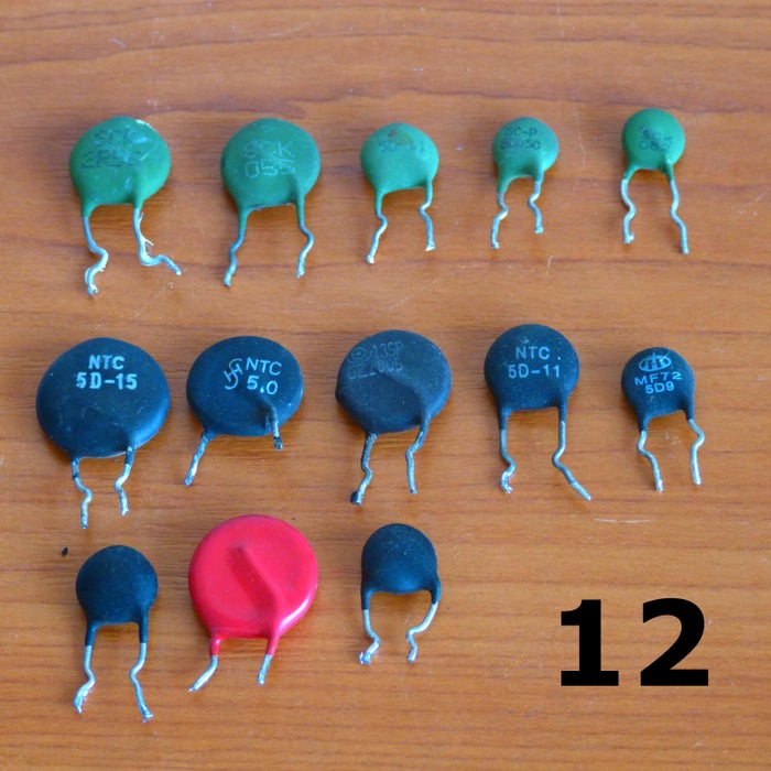
NTC is the element that limits the current through the rectifier bridge at start-up.For example, NTC type 5D-15 (photo 12) has 5ohm (room temperature) at start-up. After a period of tens of seconds, due to its heating, the resistance decreases to less than 0.5 ohm. This makes the power dissipated on this element lower, improving the efficiency of the power supply.Also, NTC dimensions are smaller than a similar limiting resistor.Usually, NTC is in good condition and can be used in similar positions in other power supplies.Step 5: Recovery of Rectifier Diodes and Rectifier Bridges
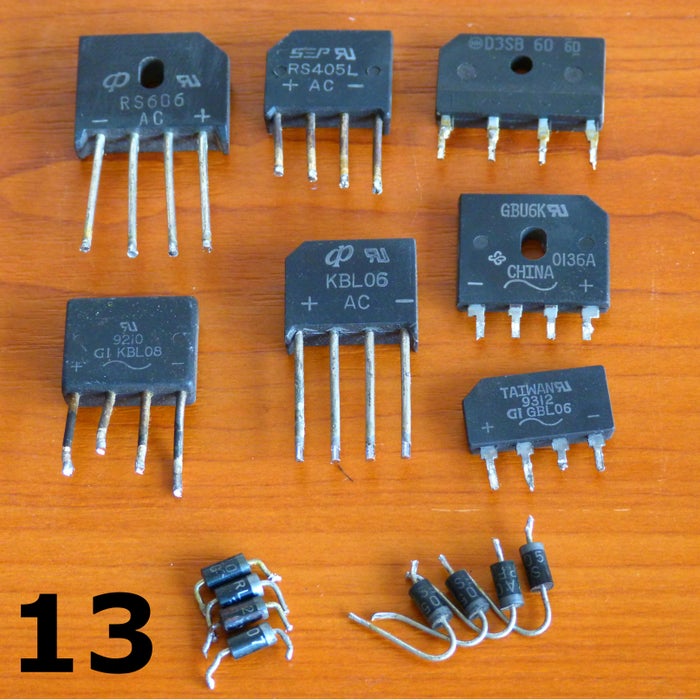
The most common form of rectifier is the one with a bridge (see photo 13).Bridges consisting of 4 diodes are rarely used.They are usually in good condition and are used in similar positions in power supply.Step 6: Recovery of Chopper Transformers and Fast Diodes
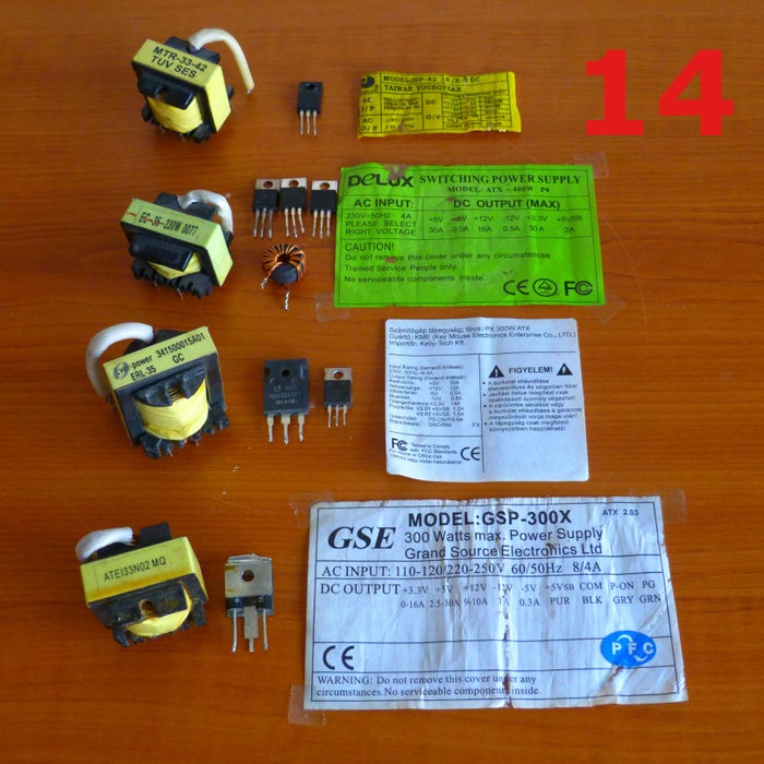
For enthusiasts of construction of switching power supplies, the recovery of chopper transformers is of the greatest utility. So I will write an Instructables on the exact identification and rewinding of these transformers.Now I will limit myself to saying that their recovery is good to be done together with the rectifier diodes in the secondary and where possible with the label on the power supply box (see photo 14). Thus we will have information about the number of secondary of the transformer and about the power that it can offer.They are usually in good condition and are used in similar positions in power supply.Step 7: Network Filter Recovery
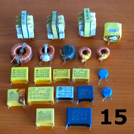
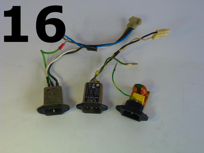
When the Network Filter is planted on the motherboard of the power supply, they will be recovered for later use as in the initial configuration (see photo 15).There are power supply variants in which the Network Filter is attached to the male couple on the box.There are two variants: without shield and with shield (see photo16).They are usually found in good condition, and can be used in the same position in power supplies..Step 8: Recovery of Switching Transistors
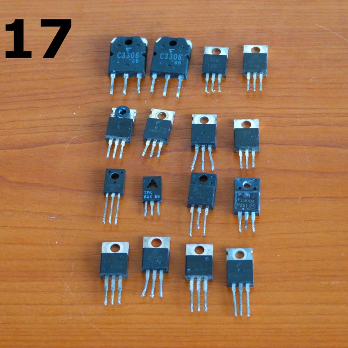
The most used switching transistors on this position are 2SC3306 and MJE13007. They are fast switching transistors at 8-10A and 400V (Q1 and Q2). See photo 17.There are other transistors that are used.They are usually found in good condition, but can only be used in the same position in half-bridge power supplies.Step 9: Heatsinks Recovery
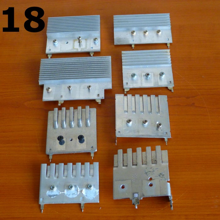
There are usually 2 heatsinks on each power supply.-Heatsink1. On it are mounted Q1, Q2 and possible 3-pin stabilizers.-Heatsink2. On it are mounted fast rectifiers for output voltages.They can be used in other power supply or other applications(audio for example). See photo 18.Step 10: Recovery of Other Transformers and Coils
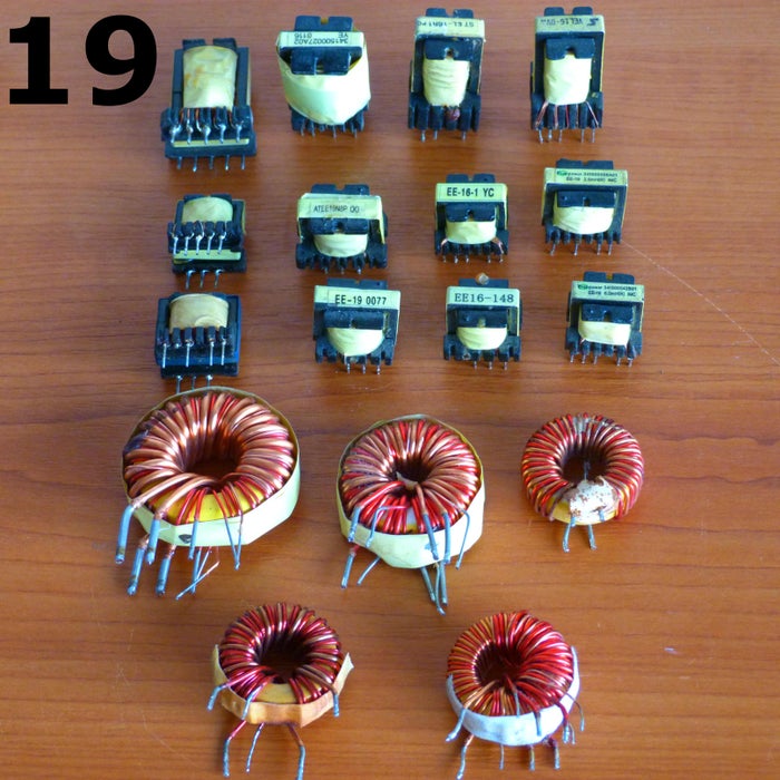
There are 3 categories of transformers or inductors that are worth recovering(see photo 19):1.L coils that are used in the original scheme as filters coils on auxiliary rectifiers.They are toroidal coils and a core is used for 2 or 3 auxiliary rectifiers in the original scheme.They can be used not only in similar positions, but also as coils in step-down or step-up power supplies, because they can withstand a continuous component of high value without saturating the core.2.TR2 transformers that can be used as a driver transformer in half-bridge power supplies.3.TRUsby, standby transformer, which can be used in the same position, as transformer in a standby source, for another power supply.Step 11: Recovery of Other Components and Materials
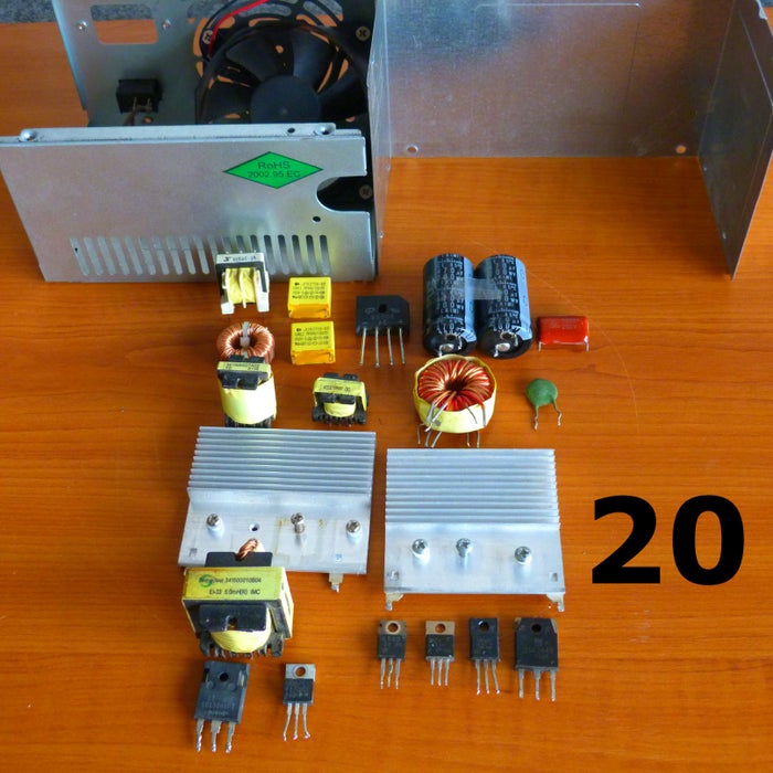
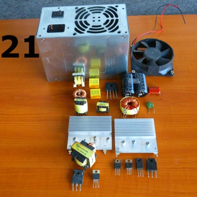
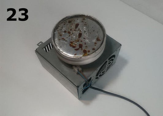
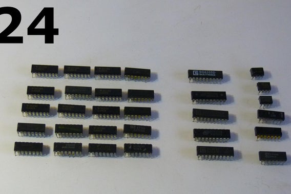
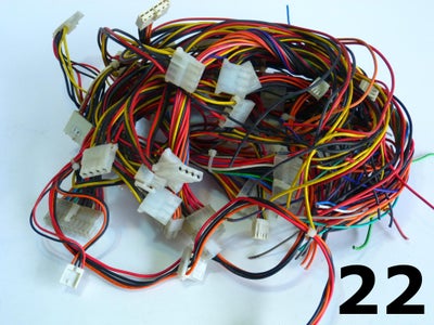 In photo 20 and 21 you can see disassembled sources and the components described above.In addition, here are two elements that can be useful: the metal box in which the power supply was mounted and the fan that cools its components.The way we used the metal box we find at:https://www.instructables.com/Power-Timer-With-Ard...andhttps://www.instructables.com/Home-Sound-System/The fans are powered by 12V DC and also have many applications. But I found a fairly large number of fans worn (noise, vibration) or even stuck up.That is why it is good to check carefully.Other things that can be recovered are the wires. Photo 22 shows the wires recovered from several power supplies. They are flexible, of good quality and can be reused.Photo 24 shows other components that can be recovered: PWM Control CI.The most used are: TL494 (KIA494, KA7500, M5T494) or those from the SG 6103, SG6105 series.Separately from these are ICs from the LM393 series, LM339, comparators that are used in source protection circuits.All of these ICs are usually in good condition, but a pre-use check is required.Finally, but not without importance, you can recover the tin with which the components of the power supply are soldered.The desoldering of the components is done with tin sucker.By cleaning it, a certain amount of tin is obtained, which is collected and melted in the tin melting bath (photo 23).This melting bath is made of Aluminum and is electrically heated. A box recovered from the power supply is used as support.Of course, it is necessary to collect a large amount of tin, which is done over time and on several devices. But it is an activity worth doing because it saves the environment and the capitalization of the tin thus obtained is quite profitable.
Step 12: Final Conclusion:
The recovery of components and materials from these power supplies is one that contributes to saving the environment, but helps us to obtain components and materials with which to do various things. Some of them I will present in the future.Some of the electronic components on the board will not be recovered, being considered obsolete or devalued. This is the case for the other components that have not been shown here and will be left on the motherboard. These will be recycled by authorized companies.


